Pupil Diameter Analyzer
The Pupil Diameter Analyzer performs epoch-based analysis of pupil diameter data.
Table of contents
Introduction
The Pupil Diameter Analyzer performs epoch-based analysis of pupil diameter data. The module performs outlier rejection and filters the data using user-specified settings and criteria. In addition, the module allows the user to amend or override the filter’s rejections. The purpose of the module is to generate smooth pupil diameter signals that are suitable for epoch-based analyses, or further processing1.
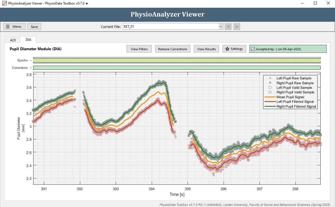
Aside from the standard epoch plot at the top, the GUI consists of the following graphs:
-
Force Reject:
The Force Reject correction graph shows the zones in which the user overrides the filter’s rejection of raw samples; i.e., the user forces the inclusion of the samples within the marked zone. Both the Force Reject and Force Accept graphs feature two bars, one for the right pupil (green-colored bottom bar) and one for the left (red-colored top bar) pupil. -
Force Accept:
The Force Accept correction graph shows the zones in which the user overrides the filter’s inclusion of raw samples; i.e., the user forces the exclusion of samples. -
Pupil Diameter:
The pupil diameter graph shows the raw and valid pupil diameter samples, as well as the interpolated and filtered pupil diameter signals.
User Corrections
The toolbox allows the user to override the previously described filters by forcing the acceptance or rejection of raw data samples, regardless of the filer and threshold violation. It is advisable to first determine the optimal automatic filtering settings for all files, then to review, and, if necessary, correct the filtering algorithm.
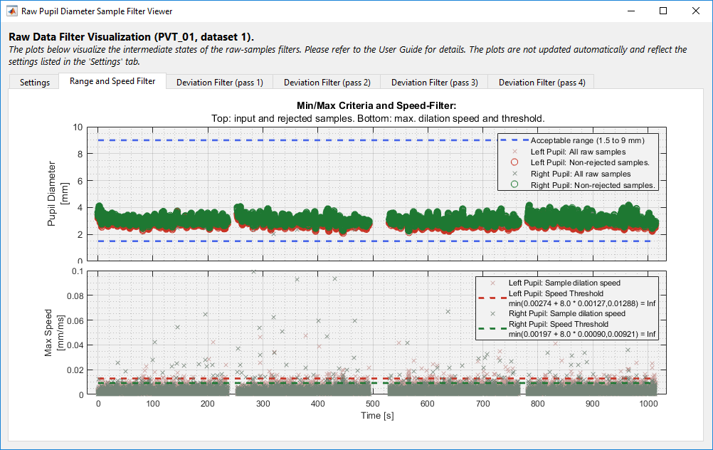
The Pupil Diameter module includes a popup window for visualizing the filter thresholds and intermediate steps, see Figure. To show, click the Show Filters button in the PhysioAnalyzer Viewer. The information in this window can be used to review the efficacy of the filter settings on the current data.
As described at the start of this section, the user can overrule the automatic sample rejection algorithm. This can be done by selecting a time section of the data by right-clicking and dragging inside the graph, then selecting one of the following actions, per eye:
-
Keep as is:
Nothing is changed for the corresponding eye. -
Force acceptance of samples in selected range:
Force that the module uses the raw samples inside the selected range, for the given eye. -
Force rejection of samples in selected range:
Force that the module discards the raw samples inside the selected range, for the given eye. -
Remove user overrides in selected range:
Remove any force-accept or force-reject zones inside the selected range, for the given eye.
The filter settings and data correction approach are the responsibility of the researcher, and are currently out of the scope of this document.
The module automatically ensures that a force-accept zone and a force-reject zone do not overlap for a given eye. As such, adding one zone where the other exists removes the overlap from the pre-existing zone. As with other modules, the user correction graphs are light green when no zones are present.
Figure 3 shows a section of pupil diameter data obtained using a Tobii Glasses II eye-tracker. It is noticeable that the system had trouble detecting the right pupil diameter between 524 and 562 seconds, resulting in a cloud of erroneous samples, which is in stark contrast to the smooth and coherent pupil diameter signals seen in the rest of the recording.
Due to the nature of the noise and the filter settings used, the erroneous right-pupil samples were not rejected by the raw data filters. Consequently, the mean pupil diameter signal was distorted by the contribution of the incorrect right-pupil filtered signal, which was generated by interpolating the erroneous right-pupil samples.
To remedy this, the user can insert a force-reject zone for the right-pupil samples covering the noisy section. This will prevent the toolbox from using any right-pupil samples within that zone. Additionally, given that the section exceeds the maximum interpolation distance, the toolbox will not generate the interpolated smooth signal for that section, for the right pupil diameter. As a result, the mean pupil diameter signal in the force-reject section will be generated solely from the left pupil data, which contains far less noise. See figures below.
Similarly, in cases where the filter rejected valid samples, and the issue cannot be easily corrected by tweaking the settings, the user can force the acceptance of rejected samples by inserting a force-accept zone.

Fast-Mode
This module features a special variation of the “fast-mode” correction feature, which can be enable thought the Menu button of the PhysioAnalyzer Viewer (more info). When Fast-Mode is enabled: left-to-right selections add Force-Reject zones, while right-to-left selections clear both Force-Reject and Force-Accept zones.
Eye Selection
By default, the Fast-Mode applies the zone-actions to all available eyes. To select a specific eye:
-
To only affect the left-eye:
Hold down Z while selecting the zone; or, hide the right-eye’s raw samples by clicking it in the legend. -
To only affect the right-eye:
Hold down X while selecting the zone; or, hide the left-eye’s raw samples by clicking it in the legend.
Zone-Type Selection
By default, the Fast-Mode creates a Force-Reject zone. To create a Force-Accept zone, hold down C while selecting the zone. This can be done in combination with the Z and X keys to insert a Force-Accept zone for a specific eye.
Processing and Analysis Pipeline
The toolbox features a robust and customizable preprocessing pipeline, which can be broken down into two steps: (1) filtering the raw data to extract the subset of valid samples; and, (2) upsampling and smoothing the valid samples. Before the filtering commences, the raw data can be multiplied by a constant value, the gain.
Step 1: Filtering the Raw Data
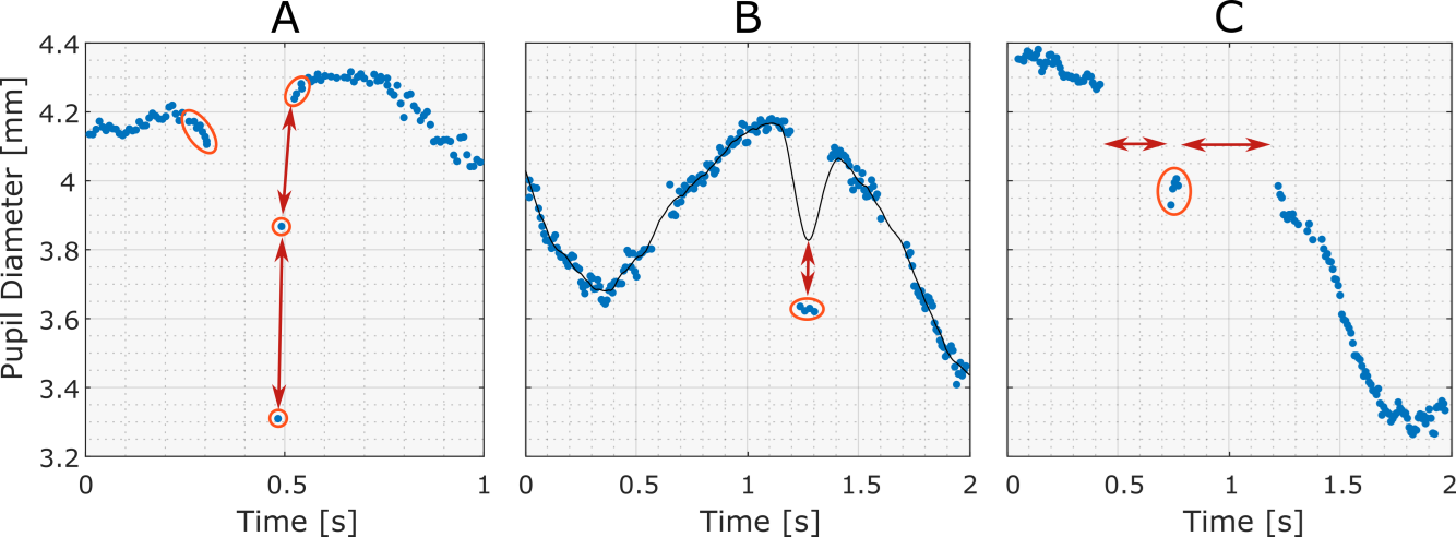
Raw eye-tracking data often contain samples that are purely the result of noise or artifacts, and therefore carry no useful information for pupil size analysis. Identifying and removing these samples, however, is not a trivial task. This filtering pipeline is aimed at identifying three types of often occurring invalid pupil size samples: (1) dilation speed outliers and edge artifacts; (2) trend-line deviation outliers; and (3), temporally isolated samples.
In addition, pupil size samples that are simply outside of a predefined feasible range can be rejected via the user specified minimum and maximum accepted values.
Removing Dilation-Speed Outliers and Edge-Artifacts
Dilation speed outliers are samples that feature a disproportionately large absolute pupil size change relative to their adjacent samples. Because the changes between samples due to actual pupil dilation and constriction are generally less than those resulting from artifacts, such as system errors or blinks, detecting outliers in these changes is an effective way of spotting and rejecting invalid samples.
To detect dilation speed outliers, the Median Absolute Deviation (MAD), which is a robust and outlier resilient data dispersion metric, is calculated from the dilation speed series, multiplied by a constant (n), and summed with the median dilation speed. Samples with dilation speeds above the threshold can now be marked as outliers and rejected.
Dilation speed filter settings:
-
Speed-filter MAD threshold [-]: The number (n) of MADs used as a threshold to reject outliers.
-
Absolute speed-filter threshold [mm/ms]:
Any samples with dilation speeds above this value are rejected. This criteria can be used if the rejection should occur according to some metric other than MADs, such as standard deviation. The absolute threshold, such as the standard deviation of the dilation speeds of all pupil diameter samples inside epochs, can be calculated using a custom MATLAB script.
After the dilation speed outliers have been removed, artifacts around gaps in the data may still remain, especially if these gaps are the result of eye blinks, which may cause pupil size underestimation due to eye-lid occlusion. Therefore, it is sensible to reject the samples that border certain gaps in the data. In order to identify ‘gaps’, the toolbox looks for sections of missing samples with durations within a specifiable range: the gap lower and upper bounds. Once these gaps have been found, samples that form its leading and trailing edges are removed.
Gap detections and edge-artifact removal settings:
-
Gap lower-bounds [ms]:
The minimum duration a gap needs to have to be classified as such. -
Gap upper-bounds [ms]:
The maximum duration a gap may have in order to still be classified as such. -
Backward gap-padding [ms]:
The duration of the section before the start of the gap in which samples are rejected. -
Forward gap-padding [ms]:
The duration of the section after the end of the gap in which samples are rejected.
Removing Trend-line Outliers
Certain eye-trackers, especially those with higher sampling rates, may produce small groups of clearly invalid samples which, since they are clustered together, are resistant to dilation speed filtering. Instead, these invalid samples can be identified by their strong departure from the signal’s trend-line, which can be generated by interpolating and smoothing the data that remain after the previous filtering steps.
Outliers in absolute trend-line deviations can then be identified and rejected in a similar manner to dilation speed outliers by feeding the absolute trend-line deviations into the MAD filter. Subsequently, a new trend-line can be generated using the now remaining samples, and the outlier detection process repeated on all samples considered in the first deviation filter pass. This multi-pass approach allows for the reintroduction of valid samples that were previously rejected due to the invalid samples ‘pulling away’ the trend-line.
These trend-line outliers can be removed in the toolbox using the Residuals filter, which features the following settings:
-
Residuals-filter passes [-]:
The number of passes that the filter will make. -
Residuals-filter MAD threshold [ms]:
The MAD multiplier; i.e., the number of MADs to use as the rejection threshold. -
Residuals filter low-pass filter [ms]:
The cutoff frequency of the low-pass filter used to generate the smooth trend-line from the non-rejected samples.
Removing Isolated and Sparse Samples
Another feature of raw pupil size samples that may indicate invalidity is their sparsity. Since a proper pupil size signal is fairly solid, with continuous gaps during blinks and look-away moments, secluded samples are likely to be the result of noise or a momentary eye-tracker glitch, such as erroneous pupil detection during shut eyes.
The toolbox can look for these sample-islands, which are clusters of samples that are temporally separated from other samples, and reject them. The sparsity filter includes the following settings:
-
Island isolation criteria [ms]:
The minimum distance used to consider samples ‘separated’. The toolbox scans raw non-missing pupil diameter samples for gaps greater than this distance, and identifies the sample-island clusters—upon which the criterion below is applied. -
Minimum allowable island size [ms]:
Once islands have been identified, those smaller than the minimum allowable size are removed.
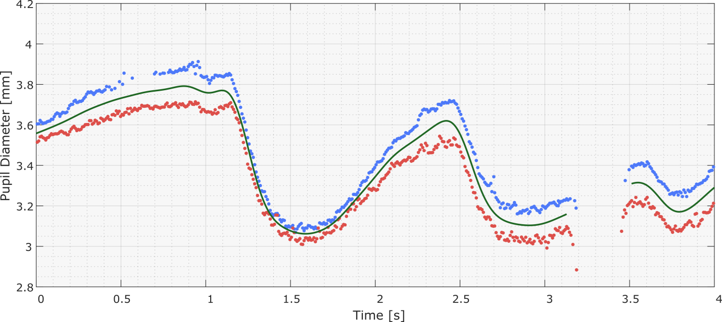
Step 2: Processing the Valid Samples
At this point, depending on whether monocular or binocular data was collected, one or two valid subsets of the original raw samples remain. If data from both eyes are available, the toolbox uses them to generate a third time-series: the mean pupil size signal. When doing so for the time-points where one pupil’s data is missing, the dynamic offset between the sizes of the two pupils is taken into account.
To increase the temporal resolution and smoothness of the data, the data-points are interpolated at 1000 Hz, then low-pass filtered at the specified cutoff frequency. Subsequently, the toolbox can set sections that were interpolated over unacceptably large gaps to ‘missing’. Valid samples processing settings:
-
Smoothing low-pass filter frequency [Hz]:
The cutoff frequency of the low-pass smoothing filter applied to the interpolated signals generated from the valid samples (the samples that were not rejected). The recommended cutoff frequency is 4 Hz . -
Maximum interpolation gap [ms]:
The maximum allowable interpolation gap. Sections that were generated by interpolating over gaps larger than this criterion are set to missing, and not used in the analysis.
Settings
The Pupil diameter analyzer assumes that the unit of the pupils size time series is mm. If this is not the case, fill in an appropriate gain value (multiplier) to transform the raw data into mm. If this is not possible–e.g. when using an eye-tracker that reports pixels (e.g. EyeLink), or when measuring the pupil area–the Toolbox will still report the results as mm.
The auto-generated list below shows the settings available in the Pupil Diameter Analyzer module:
-
General Settings:
Name, source and epoch settings for this PhysioAnalyzer.-
Analyzer prefix (tag):
The tag (name) of this PhysioAnalyzer. The tag must be unique and start with a letter, and may only contain alphanumeric characters. -
Eye-Tracking dataset number:
The channel number (index) of the signal to be analyzed. -
Generate epochs from:
Specifies how epochs are generated.
Tip: you can use infinity (‘inf’ w/o quotes) as a criteria in the settings below.
-
-
Gain and Pupil Size Restrictions:
The gain, which is the value that the raw signal is pre-multiplied by, and the minimum and maximum allowable pupil size.-
Gain (signal multiplier) [x]:
The gain is the value with which the raw signal is pre-multiplied. -
Minimum allowable pupil size [mm]:
The minimum pupil diameter criteria used to reject raw samples. -
Maximum allowable pupil size [mm]:
The maximum pupil diameter criteria used to reject raw samples.
-
-
Isolated Samples Criteria:
‘Sample-islands’ are clusters of samples that are temporally separated from other samples. The minimum distance used to consider samples ‘separated’ can be specified here. When clusters are considered separated, they need to have the minimum size specified in here; sample islands smaller than this temporal width and separated from other samples by the distance mentioned above are marked as invalid.-
Island isolation criteria [ms]:
‘Sample-islands’ are clusters of samples that are temporally separated from other samples. The ‘island isolation criteria’ specifies the minimum distance to another sample a cluster needs to have in order to be considered an island. -
Minimum allowable island size [ms]:
When islands are detected, they need to satisfy the minimum allowable size criteria–samples in clusters that don’t, are rejected.
-
-
Dilation Speed Filter Criteria:
Specify here the number of Median Absolute Deviations (MADs) to use as the cutoff threshold when applying the speed filter. Usually a value between 4 (aggressive) and 16 (permissive) works well, but this depends on the dataset and Eye-Tracker characteristics. An absolute threshold can also be set manually.-
Speed-filter MAD threshold [n]:
The number of MADs to use as the cutoff threshold when applying the speed-filter. -
Absolute speed-filter threshold [mm/ms]:
The absolute threshold of the speed-filter. If enabled, all samples with dilation speeds above the threshold are rejected.
-
-
Edge Removal Filter Criteria:
Pupil size data may contain artifacts at the edges of ‘gaps’. These artifacts are e.g. caused by the Eye-Tracker reporting the size of a pupil which is still partially occluded by the eyelid during the start or end of a blink. Specify here the duration criteria used to classify missing data as a ‘gap’, then indicate the section right before the start of the gap (the backwards padding distance) and the section right after the gap (the forward padding distance) within which samples are to be rejected.-
Gap lower-bounds [ms]:
The minimum duration a gap needs to have to be classified as such. -
Gap upper-bounds [ms]:
The maximum duration a gap needs to have to be classified as such. -
Backward gap-padding [ms]:
The duration of the section before the start of a gap in which samples are rejected. -
Forward gap-padding [ms]:
The duration of the section after the end of a gap in which samples are rejected.
-
-
Deviation Filter Criteria:
After passing through the filters described above, a subset of the original pupil size samples remain and form the input for the Deviation Filter. This filter generates a smooth trendline by lowpass filtering the remaining samples, then calculates the deviation of each sample relative to this trendline. Samples featuring a deviation outside of a threshold, which is a multiple of the median, are then removed. This process can be performed in multiple passes.-
Residuals-filter low-pass frequency [Hz]:
The cutoff frequency of the low-pass filter used to smooth the residuals-filter’s trendline. -
Residuals-filter MAD threshold [n]:
The number of MADs to use as the cutoff threshold when applying the residuals-filter. -
Residuals-filter passes [n]:
The number of passes the residuals-filter makes.
-
-
Smoothing and Interpolation Gaps:
Finally, the remaining valid samples are interpolated and upsampled to 1000 Hz, then low-pass filtered to create smooth and continuous signals. Optionally, the maximum gap over which interpolation is allowed can be specified.-
Smoothing low-pass filter frequency [Hz]:
The cutoff frequency of the low-pass filter used to smooth the interpolated pupil diameter signal. -
Maximum interpolation gap [ms]:
The maximum gap to interpolate over when generating the interpolated signal. Gaps larger than the limit are set to missing.
-
Metrics
The auto-generated table belows lists all the metrics produced by the Pupil Diameter Analyzer module.
Table 1: The metrics calculated by the Pupil Diameter Analyzer module.
| Variable: | Unit: | Description: |
|---|---|---|
| meanDia_BothEyes | mm | The mean pupil diameter, calculated per epoch from the interpolated and smoothed signal generated from the valid samples of both pupils. |
| minDia_BothEyes | mm | The minimum pupil diameter, calculated per epoch from the interpolated and smoothed signal generated from the valid samples of both pupils. |
| maxDia_BothEyes | mm | The maximum pupil diameter, calculated per epoch from the interpolated and smoothed signal generated from the valid samples of both pupils. |
| signalCoverage_BothEyes | % | The approximate percentage of the epoch in which data from the interpolated signal is available. |
| meanDia_LeftEye | mm | The mean pupil diameter, calculated per epoch from the interpolated and smoothed signal generated from the valid samples of the left pupil. |
| minDia_LeftEye | mm | The minimum pupil diameter, calculated per epoch from the interpolated and smoothed signal generated from the valid samples of the left pupil. |
| maxDia_LeftEye | mm | The maximum pupil diameter, calculated per epoch from the interpolated and smoothed signal generated from the valid samples of the left pupil. |
| signalCoverage_LeftEye | % | The approximate percentage of the epoch in which data from the interpolated signal is available. |
| meanDia_RightEye | mm | The mean pupil diameter, calculated per epoch from the interpolated and smoothed signal generated from the valid samples of the right pupil. |
| minDia_RightEye | mm | The minimum pupil diameter, calculated per epoch from the interpolated and smoothed signal generated from the valid samples of the right pupil. |
| maxDia_RightEye | mm | The maximum pupil diameter, calculated per epoch from the interpolated and smoothed signal generated from the valid samples of the right pupil. |
| signalCoverage_RightEye | % | The approximate percentage of the epoch in which data from the interpolated signal is available. |
| countRawSamples_LeftEye | - | The total number of left eye raw pupil diameter samples inside the epoch. Only Non-NaN samples are counted. |
| countRawSamples_RightEye | - | The total number of right eye raw pupil diameter samples inside the epoch. Only Non-NaN samples are counted. |
| countValidSamples_LeftEye | - | The count of the valid left eye pupil diameter samples inside the epoch. The 'valid samples' are the samples that were not rejected by the filters or the user, and were used to generate the interpolated signal. |
| meanValidSamples_LeftEye | mm | The mean of the valid left eye pupil diameter samples inside the epoch. |
| minValidSamples_LeftEye | mm | The minimum of the valid left eye pupil diameter samples inside the epoch. |
| maxValidSamples_LeftEye | mm | The maximum of the valid left eye pupil diameter samples inside the epoch. |
| stdValidSamples_LeftEye | mm | The standard deviation of the valid left eye pupil diameter samples inside the epoch. |
| countValidSamples_RightEye | - | The count of the valid right eye pupil diameter samples inside the epoch. The 'valid samples' are the samples that were not rejected by the filters or the user, and were used to generate the interpolated signal. |
| meanValidSamples_RightEye | mm | The mean of the valid right eye pupil diameter samples inside the epoch. |
| minValidSamples_RightEye | mm | The minimum of the valid right eye pupil diameter samples inside the epoch. |
| maxValidSamples_RightEye | mm | The maximum of the valid right eye pupil diameter samples inside the epoch. |
| stdValidSamples_RightEye | mm | The standard deviation of the valid right eye pupil diameter samples inside the epoch. |
Resampled Signals
When exporting the resampled epoch signals, the Pupil Diameter Analyzer resamples the filtered pupil size signals.
References
-
The filtering pipeline described in this section is largely taken from: Kret, E., & Sjak-Shie, E. E. (2018). Preprocessing pupil size data: Guidelines and code. Behavioral Research Methods, 1-7. Available at: https://rdcu.be/2QCd. ↩