Data Viewers
The Toolbox features data viewers to visualize and allow interaction with the raw data and analysis pipelines inside the PhysioData files.
Table of contents
Introduction
Data Viewers are graphical user interfaces that display data, such as graphs and tables, and allow the user to navigate and interact with the displayed data.
The PhysioData Toolbox contains two types of Viewers:
-
The Raw Data Viewer:
This viewer displays information about the raw data inside the PhysioData. To open the Raw Data Viewer, select a file in the Session Manager and click the View Raw Data button. -
The PhysioAnalyzer Viewer:
The PhysioAnalyzer Viewer is a window for inspecting and interacting with the PhysioAnalyzers inside each PhysioData file. The data of each PhysioAnalyzer is visualized in a separate tab. To open the PhysioData Viewer, select a file in the Session Manager and click the View Analyses button.
The Data Viewers feature a navigation bar just below the banner, which can be used to change the file currently displayed in the Viewer.
Graph Interactions
The graphs shown in the Raw Data and PhysioAnalyzer Viewer windows all exhibit the same general zooming and panning behavior, which is controlled using the scroll wheel, and the left and right mouse buttons.
Zooming and Panning
The following zooming actions can be performed when interacting with axes:
-
Selection Zooming:
Right-clicking inside a graph and moving the mouse while holding down the right mouse button creates a transparent blue selection rectangle, releasing the mouse button then zooms in to that rectangle. -
Horizontal Zooming:
Zooming the horizontal axis is done by scrolling the mouse scroll-wheel; scrolling up zooms in and scrolling down zooms out. -
Vertical Zooming:
Zooming the vertical axis is done by pressing the mouse scroll-wheel, then scrolling it while holding it down; scrolling up zooms in and scrolling down zooms out. -
Dragging:
You can drag the graph left, right, up and down by clicking the mouse scroll-wheel button while the cursor is positioned inside the graph, then holding the button down and moving the mouse. -
Horizontal Panning:
You can pan horizontally—i.e., shift the graphs left or right—by scrolling up or down while holding down the right mouse button. -
Reset:
Double-click on a graph using the left mouse button to reset the zoom. This will zoom out to a level where all data points fit inside the graph.
Graph Context Menu and Legend
Each module creates its own customized set of graphs and plots. Generally, right-clicking inside a graph without moving the mouse opens a menu with zooming and PhysioAnalyzer-specific analysis and interaction options.
When a graph has a legend, the legend entries can be clicked to hide the corresponding lines. Hiding unnecessary lines may improve performance when scrolling and panning long recordings.
Zooming and Panning with Keyboard
The graphs can also be controlled using the keyboard. However, this feature is still in development and may be slow and buggy. The keys currently only work in the PhysioAnalyzer Viewer, and you can’t combine keys.
-
Keyboard Panning:
WASD/arrows for up, down and sideways panning. Hold down SHIFT for faster movement. -
Keyboard Zooming:
ALT + WASD/arrows for zooming. -
Fit Y-axis to contents:
q -
Zoom out completely:
e
Raw Data Viewer
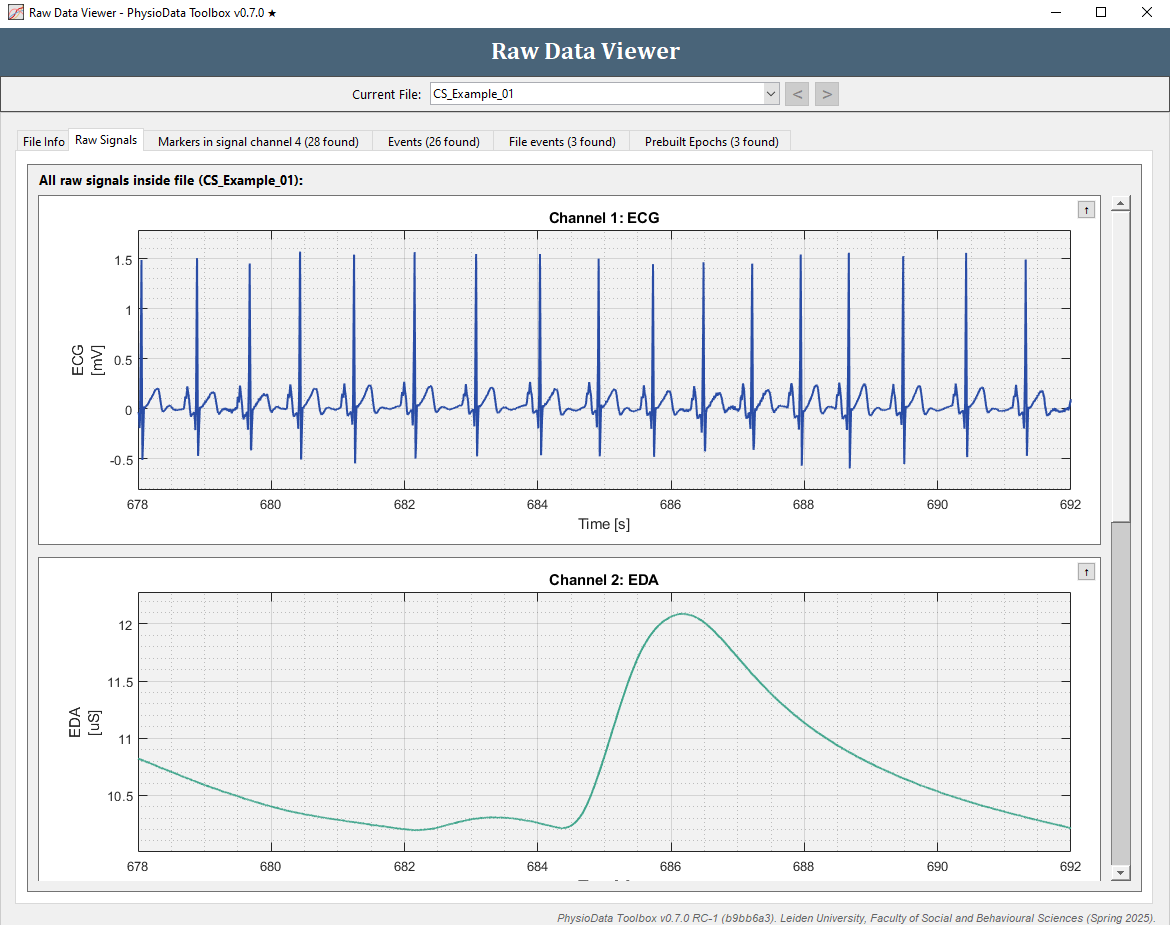
The Raw Data Viewer visualizes the raw data inside a PhysioData file. For more information about raw data, see the Session Manager section. The Raw Data viewer is launched using the View Raw Data button in the Session Manager.
The viewer consists of the following tabs:
-
File Info:
Information about the PhysioData file are displayed in the File Info tab. -
Raw Signals:
All signals are plotted in their raw form in the Raw Signals tab. It may be necessary to scroll down to see all channels. Each graph can be collapsed or re-expanded by clicking the button with the arrow in the top right corner of the graphs panel. -
Markers:
The toolbox automatically classifies a raw signal as a marker signal if it only contains non-negative integers with a max value of 65535. Signals classified as a marker signal are automatically analyzed and the detected markers are visualized and tabulated. -
Events: Events, if present, are plotted and tabulated in the Events tab.
-
File events:
File events are plotted and tabulated in the File events tab. -
Eye Tracking Dataset #:
Each eye-tracking dataset, if present, is visualized in its own tab, with each type of eye-tracking data occupying a subtab:-
Pupil Diameters:
The raw pupil diameters are visualized as a scatter plot, with each dot representing a sample point. -
Gaze & Fixation Data:
Both the gaze and fixation coordinates are visualized in an XY map, per snapshot. The snapshot image, if present, is also displayed in the graph. Note that gaze and fixation data is currently not included in the conversion to PhysioData files when using the File Converter to convert EyeLink .edf files or EET .gazedata or .txt files. -
Areas of Interest:
The AOIs are plotted as a series of horizontal bars, with each bar signifying the duration of a single hit. Like gaze and fixation data, AOIs are visualized per snapshot. -
Events:
Each eye-tracking dataset can contain its own set of events. -
Scored Sections:
Scored sections are visualized in a similar manner to AOIs, but are independent of snapshots. Note that scored sections are currently not included in the conversion to PhysioData files when using the File Converter to convert EyeLink .edf files or EET .gazedata or .txt files.
-
-
Prebuilt Epochs:
Pre-generated epochs inside the PhysioData files, if present, are plotted and tabulated in the Prebuilt Epochs tab.
The PhysioAnalyzer Viewer
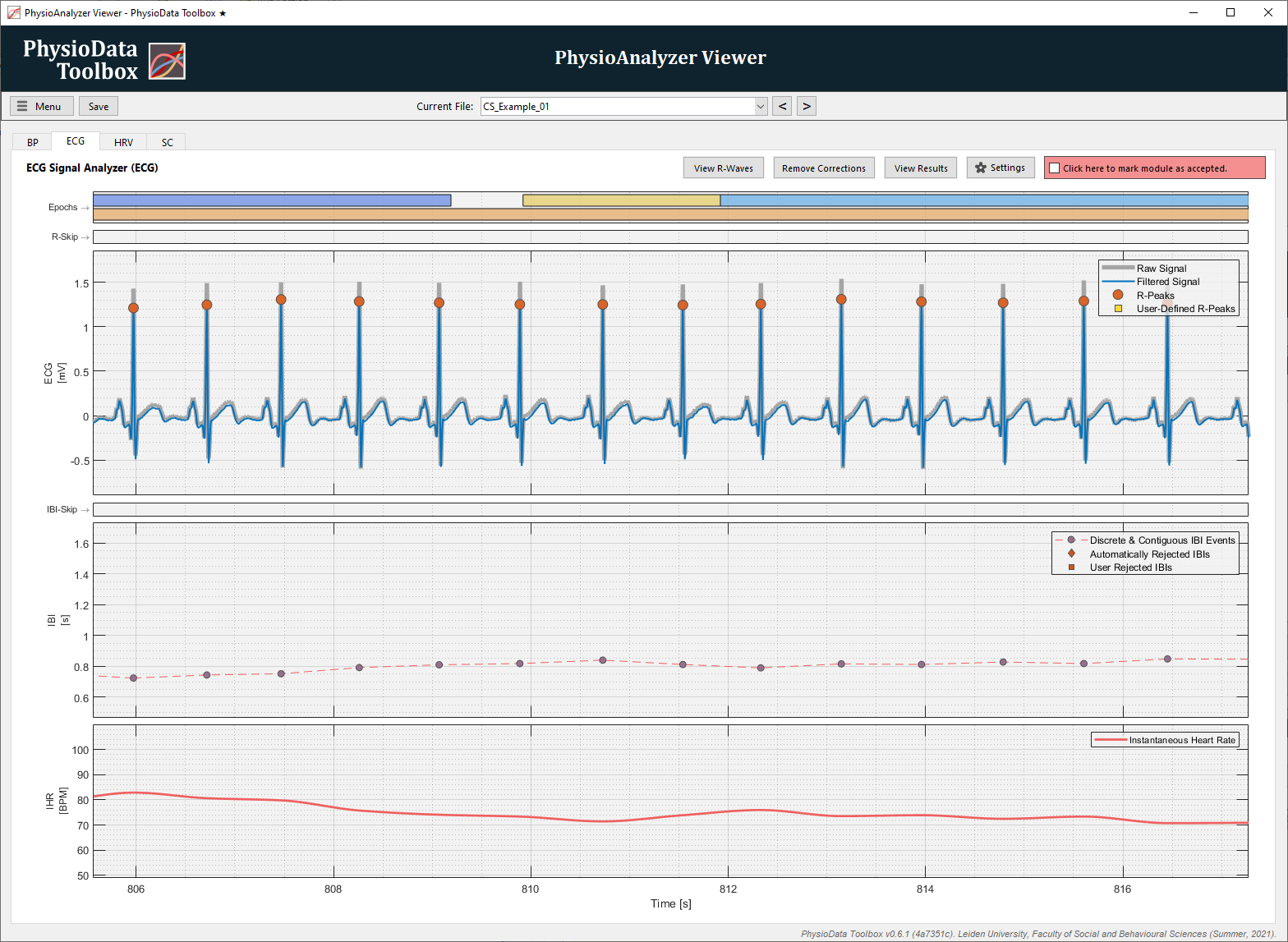
The PhysioAnalyzer Viewer generates one tab for each PhysioAnalyzer inside the current PhysioData file. The contents of the tabs are then custom generated by the PhysioAnalyzers. The PhysioAnalyzer viewer is launched using the View Analyses button in the Session Manager.
User Correction Zones
The standard method for correcting data in the toolbox involves the user defining special correction zones, within which the toolbox treats the data points differently; e.g., by disregarding detected peaks, or skipping the raw data and interpolating over the section instead. Once a correction zone has been selected, a dialog—the Section Editor—pops up presenting the available correction options.
Defining zones rather than having corrections be associated with specific features allows the State of the PhysioAnalyzer to be independent of its Settings, which in turn allows the settings to be changed without invalidating the corrections.
User correction zones are plotted as bars in one or more Corrections Graphs. These thin axes display the sections where the user inserted a correction zone. Each PhysioAnalyzer determines what corrections the user may apply, and how these corrections are used. A light green colored corrections-graph indicates that the user did not enter any correction zones in that particular axes. A green-colored bar indicates that there are correction zones present, which are usually plotted using red bars.
Fast-Mode
Some modules support Fast-Mode, which uses the selection direction to determine if a zone is to be added or removed. Fast-Mode can be enabled through the Menu button in the top-left corner of the PhysioAnalyzer Viewer (info). In Fast-Mode, the Section Editor does not appear, instead, the correction zone is immediately created thereby allowing faster data correction:
-
Adding a correction zone in Fast-Mode:
Left-click in the graph, then drag to the right. -
Removing a correction zone in Fast-Mode:
Left-click in the graph, then drag to the left.
Not all modules support Fast-Mode.
Menu
The Menu button in the PhysioAnalyzer Viewer offers the following options:
-
Automatically plot all tabs: When this option is checked, data in all tabs are plotted when the PhysioAnalyzer Viewer is opened as opposed to when the tab is clicked on.
-
Use Fast-Mode selection when possible: Click to enable or disable Fast-Mode. This setting applies to all opened PhysioData Viewers, and persists until the Toolbox is closed.
Tab Toolbar
Each tab has a toolbar displaying the PhysioAnalyzer type and its tag, and features an Accepted Checkbox, and the following buttons:
-
Remove Corrections:
Removes all user corrections in the current PhysioAnalyzer; i.e., it resets the PhysioAnalyzer’s state. The settings, however, keep their current parameters. -
Settings:
Opens the settings window for the current PhysioAnalyzer. Only the settings in the current PhysioAnalyzer are affected by changes made here. Not all settings can be changed in the individual PhysioAnalyzers; the tag, and Epoch or Event Definitions, for instance, must be changed using the PhysioAnalyzer Creator in the Session Manager. -
View Results:
Opens a window containing a table showing the Epoch or Event analysis of the current PhysioAnalyzer. Multiple of these windows can be opened, and the tabulated results are ‘analyses snapshots’; i.e., they are not updated when the PhysioAnalyzer is changed.
Accepted Checkbox
The Accepted Checkbox can be used to mark PhysioAnalyzers as ‘reviewed’ or ‘accepted’. This feature exists purely for user reference as it does not influence how, or if, the PhysioAnalyzer is analyzed. Changing the settings, or adding or removing corrections, does not reset the accepted status.
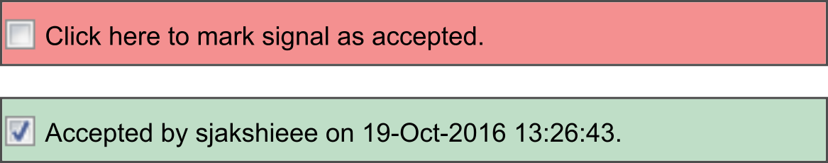
The accepted checkbox is located in the PhysioAnalyzer Viewer, in the op right corner of the tab, as seen in the Figure above.
Epoch and Event Graphs
Epochs, which are sections within a signal, are usually plotted above graphs, and have their time-axis linked to the graphs below them. Epochs are visualized as rectangles, with their horizontal width indicating their span. Their colors are pseudo-randomly chosen, and their height and thickness do not carry any information. In case epochs overlap, they are stacked vertically so that they can be differentiated.
Certain analyzers make use of Events rather than Epochs. Events are discrete—i.e., they have no duration—and are visualized with colored triangles.
Clicking on an epoch rectangle or an event triangle opens a window displaying its information.
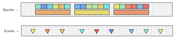
The epoch and event graphs are located in the PhysioAnalyzer Viewer, above the other axes, as seen in the Figure above.