Epochs
Epoch are relevant time segments within a recording. The Toolbox can automatically detect epochs based on predefined rule-sets, and perform descriptive analyses on them.
The Epoch definition system was renewed in v0.6. If you are already familiar with how epochs worked in v0.5, please read this section for a summary of the new features.
Table of contents
Introduction
One key feature of the Toolbox is its ability to automatically segment data into relevant sections, aka epochs, for analysis. This automatic segmentation occurs by applying a user-defined rule-set to the data inside a PhysioData file, and resolving that into epochs. The rule-set, aka epoch definition, defines how each epoch must be constructed by referencing events, markers, etc. inside the file. These data are referred to as Referenceable Events.
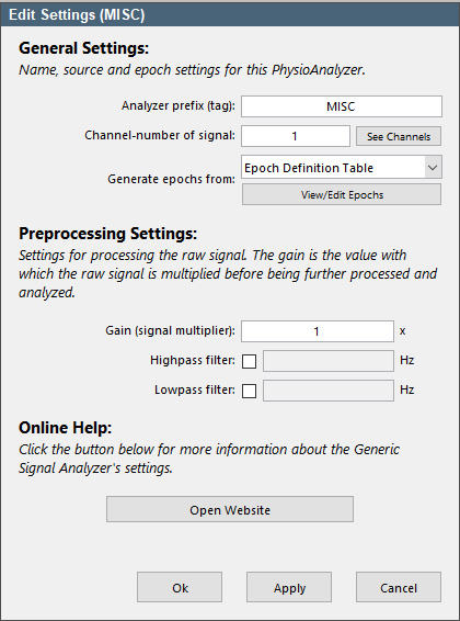
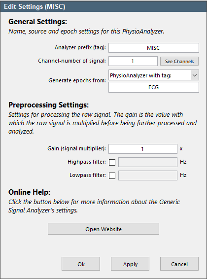
In the Toolbox, epochs are tied to the PhysioAnalyzer modules. Each PhysioAnalyzer has a setting labeled Generate epoch from and a drop down menu allowing the user to select Epoch Definition Table or PhysioAnalyzer with tag. If the former is selected, the module will generate its own epochs based on the epoch definition table provided; or, if the latter is selected, the module copies epochs from another module, selected via its tag.
Next to analyzing epochs generated using an epoch definition, the Toolbox will also analyze pre-made epochs saved in the PhysioData file.
Referenceable Events
Referenceable events are moments inside a recording that are logged for the purpose of marking relevant events, and that the Toolbox can reference for the purpose of generating epochs. The Toolbox automatically creates these referenceable events from labels, events, markers, sections, etc.
Each referenceable event has the following properties
-
Value:
The value of the referenceable event refers to its contents: e.g., a marker has a numeric value; an event has a word or sentence, etc. -
Time:
The time of the referenceable event is its timestamp; e.g. the time associated with an event, or the time a marker was received. For each referenceable event, its time property reflects the timestamp of its onset. -
Duration: The duration of a referenceable event refers to the time interval between its onset and its offset. In the case of markers, it would refer to the interval between when the marker assumes its value and releases it. When a referenceable event is discreet, i.e. it consists of a single time point, its duration is zero.
-
Occurrence:
The occurrence of a referenceable event refers to the ordinal number (1st, 2nd, etc.) of that event’s value within the set.
Referenceable events are always ordered chronologically.

As an example, take the 15 second recording shown in Figure 3, where 5 events were logged:
-
Event 1:
The first event has the value ‘Label A’, a time of 2 s, a duration of zero, and an occurrence of 1 (it is the first label with value ‘Label A’). Note that this event is discrete, and therefore has a duration of zero. -
Event 2:
The second event has the value ‘Label B’, a time of 4 s, a duration of 5 s, and an occurrence of 1 (it is the first label with value ‘Label B’). Note that this event is not discrete, and therefor as a positive duration, and is plotted as a section. -
Event 3:
The third event has the value ‘Label C’, a time of 10 s, and an occurrence of 1. -
Event 4:
The forth event has the value ‘Label D’, a time of 12 s, and an occurrence of 1. -
Event 5:
The fifth event has the value ‘Label C’, a time of 14 s, and an occurrence of 2; i.e., it is the second label with that value.
Markers
One common technique for logging events is to record markers, aka triggers, in a separate channel alongside the physiological signals. These markers are usually sent by the task-pc to the recording device (e.g. BIOPAC), and assume different values to mark different events in the recording. The Toolbox automatically detects marker channels and converts them into referenceable events, with the same properties as described previously. As such, the Toolbox documentation may refer to markers as events.
Markers are converted into referenceable events using the following rules:
- A signal is considered a marker channel if it is more that 75% flat, and has only non-negative integer values less than or equal to 65535.
- A marker is defined as a contiguous section in the signal with an integer value of 1 or higher; i.e., a marker cannot have a value of 0. A zero in the signal is simply interpreted as the absence of a marker.
- If a marker channel starts with a non-zero value, that section is not classified as a marker. Markers start being classified at the first value-change that produces a non-zero value. This is done to prevent marker values present before the task starts (but when the recording is already taking place) from being classified as markers. As a result, if the signal starts with a non-zero value, then goes to zero, that time point cannot be referenced as it is neither the end nor start of any marker.
- If a marker channel holds a value only for a single sample, that value is not classified as a marker. This is done to prevent very short intermediate values from being classified as markers.
- Markers are transformed into referenceable events with numeric values.
Even though markers are converted to standard referenceable events by the Toolbox, they are visualized as continuous signals, since that is how they were originally recorded. Referenceable events produced from markers are never discrete.
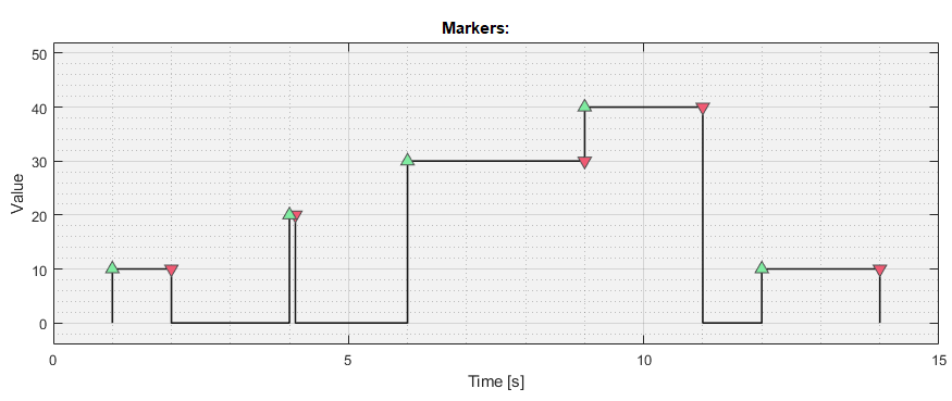
The example marker channel visualized in Figure 4 features the following markers:
-
Marker 1:
The first marker has a value of 10, a time of 1 s, a duration of 1 s, and an occurrence of 1. -
Marker 2:
The second marker has a value of 20, a time of 4 s, a duration of 0.1 s, and an occurrence of 1. -
Marker 3:
The third marker has a value of 30, a time of 6 s, a duration of 3 s, and an occurrence of 1. Notice that markers don’t have to end at zero, but end at any change in value, which if not zero, corresponds to the onset of the next marker. -
Marker 4:
The fourth marker has a value of 40, a time of 9 s, a duration of 2 s, and an occurrence of 1. -
Marker 5:
The fifth marker has a value of 10, a time of 12 s, a duration of 2 s, and an occurrence of 2. it is the second marker a the value of 10.
Defining Epochs
To create an epoch, two time points must be found: the epoch start time and the epoch end time. As such, an epoch can be defined by specifying its name, as well as where its start and end should be placed given the referenceable events in the file. Specifying how to separately resolve the start and end times of a single epoch, therefore, involves the user providing an answer to the following questions, twice:
Which set of referenceable events should the Toolbox use?
Within that set, events with what values should be extracted?
Of those extracted events, exactly which occurrence should be used?
Taking that specific event as a reference, where should the time point be placed?
In the Toolbox, the data that allows the resolution the questions above must are encoded in an Epoch Definition Table.
Epoch Definition Table
A definition for an epoch is built from three basic components: the epoch name; the start time definition; and the end time definition. The last two each resolve to a certain time in the recording, and are encoded using four parameters that the user must specify, the: channel, value, occurrence, and delay. These parameters, listed below, correspond the questions mentioned above:
-
Channel:
The channel indicates which set of referenceable events should be used to resolve the current time point. See the File-Converter documentation for info about how referenceable events are created from various data formats. The channel can be specified as:-
number:
If a number is filled in, the Toolbox will use the markers found the that channel; e.g., specifying channel =4, makes the Toolbox use the markers in signal channel 4. -
events:
Ifeventsis filled in, the Toolbox will use the events associated with the signals. For data converted from AcqKnowledge .acq files, this corresponds to the labels. For data recorded with VU-DAMS system, this corresponds to all events, labels and messages in the 5fs file. In addition toevents;event,labelorlabelswill do the same, and regardless of capitalizations. -
et.events:
Ifet.eventsis filled in, the Toolbox will use the events in the eye-tracking data. When using data recording with Tobii EET, the File Converter can automatically generate these events based on the variables (columns) in the gazedata file. When analyzing Eye-Link data, these events correspond to the messages sent to the eye-tracker. -
file:
Iffileis filled in for the channel, the Toolbox will use events it has automatically generated for the file. These include one event at the start of the file (t = 0) with the valueSOF; one at the end of the file with the valueEOF; and one event with valuefilethat spans the whole recording. -
epochs:
Epochs are also referenceable events, and can be used to define new epochs. Ifepochsis filled in, the Toolbox will extract epoch(s) with names that match the specified value.
-
-
Value:
The value parameter specifies the value used to extract the desired referenceable events. It can be a number or a string. For instance, value =10refers to all events (e.g. markers) with the value 10. Which of those need to be referenced is then decided by the occurrence. Similarly, value =Label Arefers to all events with that value Label A. -
Occurrence (aka Occur):
After events have been retrieved from the specified channel and filtered by matching them to the specified value, the desired event is selected by specifying its occurrence. For instance, specifying channel =1, value =10and occur =2indicates that from the markers in channel 4, the second occurrence of the marker with value 10 needs to be selected. -
Delay:
Once an event is selected, the delay specifies where the time-point must be placed relative to the time-stamp of the event. For instance, a delay =10states that the time point, be it the epoch start or end, must be placed 10 second after the event time. Stating delay =10would place the time point 10 seconds before the event. Additionally, the keyworddurcan be used to refer to the duration of the event. For instance, stating delay =durwill place the time-point at the end of the event; delay =dur / 2will place it in the middle of the event span; and delay =dur - 10will place it 10 seconds before the end (regardless of the start time).
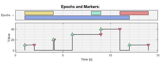
As an example, let’s say we want to create the following four epoch based on the markers in Figure 4:
-
Epoch 1:
The first epoch must start at the first marker with value 10 (Marker 1), and end at the first marker with value 20 (Marker 2) -
Epoch 2:
The second epoch must start one second before the end of the first marker with value 10 (Marker 3), and end at the end of that same marker. Note that the end of a marker, or any referenceable event, is its timestamp offset by its duration. -
Epoch 3:
The third epoch must start at the end of the first marker with value 40 (Marker 4), and end at the end of the second marker with value 10. -
Epoch 4:
The fourth epoch must start at the start of the first marker with value 10 (Marker 1), and end at the second marker with value 10 (Marker 5).
In all cases, assume that the markers are located in channel 4. A table can now be built to define epochs by stating the epoch name, and two sets of the four parameters described above; one for the epoch start, and one for the epoch end.
Table 1: Epoch definition example.
| epochName: | startChannel: | startValue: | startOccur: | startDelay: | endChannel: | endValue: | endOccur: | endDelay: |
|---|---|---|---|---|---|---|---|---|
| Epoch_1 | 4 | 10 | 1 | 0 | 4 | 20 | 1 | 0 |
| Epoch_2 | 4 | 30 | 1 | dur-1 | 4 | 30 | 1 | dur |
| Epoch_3 | 4 | 40 | 1 | dur | 4 | 10 | 2 | dur |
| Epoch_4 | 4 | 10 | 1 | 0 | 4 | 10 | 2 | 0 |
An epoch definition table, as presented above, can be applied to different files, and will always generate the right epochs based on each file’s markers. To help users build epoch definition tables, the Toolbox includes an Epoch Builder GUI.
Epochs may only exist if they have a duration of 10 ms or more; i.e., their end time must occur 10 ms or more after their start time. The epoch will result in an error otherwise. The Toolbox places no other restrictions on epoch times; they may start and/or end before and/or after the recording.
Advanced Epoch Definition Features
The Toolbox’s epoch resolution engine can make use of numeric ranges and regular expressions when filtering values, and can reference multiple occurrences and delays in a single epoch definition. As such, epochs don’t have to be defined one by one, and explicitly.
Specifying the Values
The value parameter can be specified as a number or a string, but also as a numeric range, a numeric set, or a regular expressions. This allows the value-filtering step to match various events that don’t have the exact same value, or that have a value containing ‘non-conforming’ section (e.g. an event with a timestamp in the value, which will vary randomly between recordings).
Specifying the value parameter as:
-
A number:
When a single number is specified—e.g. value =10, the events with exactly those values are used. -
A numeric set:
When a numeric set is entered—e.g. value =[10:20]or value =[100 200], all events values that are a member of that set is matched. In the first case, all events with the values 10 through 20, and in the second, all events with values 100 or 200. Standard MATLAB syntax can be used to specify numeric sets. -
A string:
When specifying the value as a string—e.g. value =Label A, only labels with values that completely match (case sensitive) are used. Note that leading and trailing white spaces are ignored. -
A regular expression:
When the value is specified as a string enclosed in ^ and $—e.g. value =$Label [A-Z]^, it is treated as a regular expression, and any events with values matching the expression are used. Note that both the ^ and $ anchors are used as part of the expression. See MATLAB help for more information about regular expressions. Feel free to email the developers for help generating regular expression patterns.
Multiple Occurrences
Similar to specifying numeric values, occurrences can be specified as a single number or as a set. Additionally, the keyword last can be used, which will resolve to the index of the last event that matches the specified value. The usage of last is equal to the MATLAB usage of end (which can also be used instead of last). As an example, when specifying occur = 1:last, all occurrences of the events that match the specified value are selected.
Note that when the value is not strictly specified—i.e., it is specified as a regular expression or a numeric range—the selected events may not have exactly the same value, but will still be ordered sequentially. For instance, when using these markers, and specifying value = [1:255], then occur = [2 3], the second and third of all the markers with values between 1 and 255 are selected; i.e., the 2nd and 3rd markers in the list. These are the occurrences 2 and 3 of the events that match the value specification ([1:255]), even though those events themselves don’t have occurrence 2 and 3; they are both the first occurrence of their exact values. The occur parameter targets the order of the events that were selected by the value filter, thus if the value is not strictly specified, the occurrences inside the set produced by the value filter might differ from the event occurrences.
Occurrences must resolve to positive integers, and basic MATLAB functions can be used, like max(), min(), ceil(), floor(), round(), etc.
Relative Occurrences
As of version 0.7.0, the endOccur can be defined relative to the that epochs’s start time by appending the occurrence with the AFTER keyword. For instance, filling in 1 AFTER in endOccur will find the first occurrence after the epoch’s start time that matches the endValue.
When using the AFTER keyword, only scalar occurrences in endOccur are supported; e.g., an endOccur of [1 2] AFTER will produce an error. However, the startOccur (or startDelay) can be non-scalar, in which case–when using the AFTER keyword–the endOccur will be applied to each resolved start time. For instance, say a file contains 10 markers with value 20 indicating the start of an epoch, each followed by a marker with a value of either an 21 or 22, indicating the end of that epoch. These epochs can be defined using the startValue of 20, a startOccur of 1:last, an endValue of [21 22], and an endOccur of 1 AFTER.
Similarly, the BEFORE keyword can be used in the startOccur to indicate the start occurrence needs to be limited to the time before the end of the epoch; e.g., a startOccur of last BEFORE will match the last event that matches the startValue before the end time, or times if the end definition resolves to multiple times.
Multiple Delays
The delay parameter can be specified as a single number or as a vector; or as a formula that resolves into one of the two. When specified as a single number, that delay is applied to all events that match the value and occurrences specified in the definition. For instance, if the value and occurrence parameters produce 2 events, and the delay is specified as delay = 5, then two time points will be produces; 5 seconds after both events.
When the delay is specified as a vector, then all delays are applied to all events. For instance, if the value and occurrence parameters produce 2 events, and the delay is specified as delay = [5 10], then four time points will be produces; 5 and 10 seconds after both events. Multiple delays will be applied occurrence by occurrence; e.g., the delay [5 10] when applied to two events (Event_A and Event_B), will produce the time sequence: Event_A + 5; Event_A + 10; Event_B + 5; Event_B + 10.
When specifying multiple delays, standard MATLAB syntax can be used, including basic functions like max(), min(), ceil(), floor(), round(), etc. Additionally, the keyword dur can be used, which resolves into the duration of the event that the delay is applied to.
Pairing Multiple Start and End Times
The epoch start and end definitions are resolved separately, then paired up to form epochs. If the start or end definition produces more times than the other, the un-pairable times will produce epochs with errors.
Epoch Data
When an epoch analysis is run and exported, epoch data, which includes each epoch’s name, start and end times, as well as extra metadata, is included in the output. The extra metadata contains data about the epoch definition resolution, and the events referenced. This includes the actual values, durations and occurrences of the referenced events, as well as the delays applied. Since these parameters don’t have to be specified explicitly, the actual value that these parameters resolve to may emerge only after applying the epoch definition to the a file.
Epoch Builder
The Toolbox contains an Epoch Builder to help users build and test epoch definition tables. It is launched whenever users click View/Edit Epochs button in the PhysioAnalyzer settings panel.
The Epoch Builder can be split into two main sections: the outer window and the tab group. The outer window contains the banner on top (where it says Epoch Builder), the file bar below that, and the buttons on the bottom. The tab group contains tabs that display the current epoch definition table and its associated data.
Note, the Epoch Builder can only manage epoch definition tables with 100 rows or less.
Outer Window
In the outer window, under the banner, lies the File Bar. It shows the current Test File, which is the file used to resolve the current epoch definition when the Generate Epochs button is clicked.
In the left side of the outer window banner lies the Menu button, which has the following options inside the Epoch Definition sub-item:
-
Copy Table:
Copies the current epoch definition table to the clipboard, allowing it to be pasted and edited in Excel. -
Paste Table:
Overwrites the current definition table with the contents of the clipboard. This allows tables to be copied from Excel. -
Load From File:
Overwrites the current definition table with the contents of an Excel file.
At the bottom of the window lies three buttons:
-
Save and Exit:
Accepts and saves the current epoch definition, and exits the Epoch Builder. -
Reset:
Undoes all changes and reloads the original epoch definition present when the builder was launched. -
Cancel:
Discards all changes and closes the Epoch Builder.
If the Epoch Builder window is closed manually, all changes are discarded.
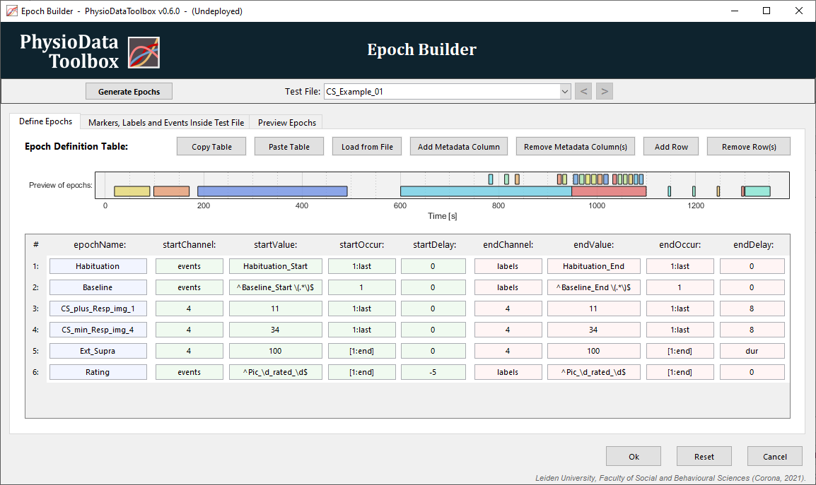
Tab 1: Define Epochs
The first tab, labeled Define Epochs, shows the epoch definition table and allows users to edit it.
The tab contains the following buttons:
-
Add Metadata Column:
Adds a metadata column to the epoch definition table. -
Remove Metadata Column(s):
Removes one or more columns from the epoch definition table. -
Add Row:
Add a new row to the bottom of the epoch definition table. -
Removes Row(s):
Removes one or more rows from the epoch definition table. -
Generate Epochs:
Regenerates the epochs preview by applying the current epoch definition to the test file, as specified by the Test File popup menu. Note that the button is disabled if no files are loaded into the Session Manager.
Below the buttons, the epochs that the current epoch definition table produces when applied to the current file are visualized. This includes epochs already present in the file. The plot is refreshed whenever the ‘Generate Epochs’ button is clicked, and is only visible if files are loaded into the Session Manager.
Below that, in the main section of the Define Epochs tabs, is the Epoch Definition Table. The first column (light blue) contains the epoch names, with the next 4 (light green) containing the start time definition, followed by the end time definition (light red). Subsequent columns contain optional metadata (light yellow). Users can freely modify the contents of the cells, or can use the cells’ right click menus. If a row in the epoch definition table produces one or more errors, they are shown in the table under the concerning row.
Epoch Definition Menus
Right clicking the cells in the epoch definition table reveals a context menu. The contents of the menu reflects the actual contents of the current test file, and where applicable, is determined by the value of one or more other parameters.
-
Channel:
When right-clicking the startChannel or endChannel cells, the first menu item lists the sets of referenceable events in the file. This determines what values are shown. -
Value:
When right-clicking the startValue or endValue cells, the first menu item lists all the unique values present in the selected set, specified by either the startChannel and endChannel, respectively. The number of occurrences for each value is also shown. The items below present additional options, such as referencing ‘all events’. -
Occur:
When right-clicking the startOccur or endOccur cells, the first menu item lists all the occurs matching the concerning value parameter. Additional items allow e.g. the selection of all occurrences. -
Delay:
When right-clicking the startDelay or endDelay cells, a set of delay options are presented. Below that, the option to slice the event is offered, see Slicing Epochs.
The context menus also allow the current table row to be deleted or duplicated; and the start or end definitions to be copied from one to the other.
Slicing Epochs
At times, users may wish to slice large epochs into smaller sections. To do this, the large epochs must first be defined in the epoch definition table (or must already be present in a file). The startChannel and endChannel must then be set to epochs so that these epochs can be referenced, and the startValue and endValue parameters, in combination with startOccur and endOccur, can be used to specify the name and occurrences of the to be referenced epoch(s).
If the startDelay is set to 0, and the endDelay to dur, new epochs spanning the entirety of the referenced epoch(s) are created. Similarly, if the delays are set to [0 10] and [10 dur], two new epochs are created: one spanning the first 10 seconds of the referenced epoch(s), and the other starting after the first, and ending where the referenced epoch(s) end.
To fully slice a epoch, right-click the startDelay or endDelay cells after the startChannel and endChannel have been set to epochs, and the value and occur parameters have been used to select the epoch(s) to be sliced. The Toolbox will then present a dialog with slicing options, and will automatically generate the necessary startDelay and endDelay parameters.
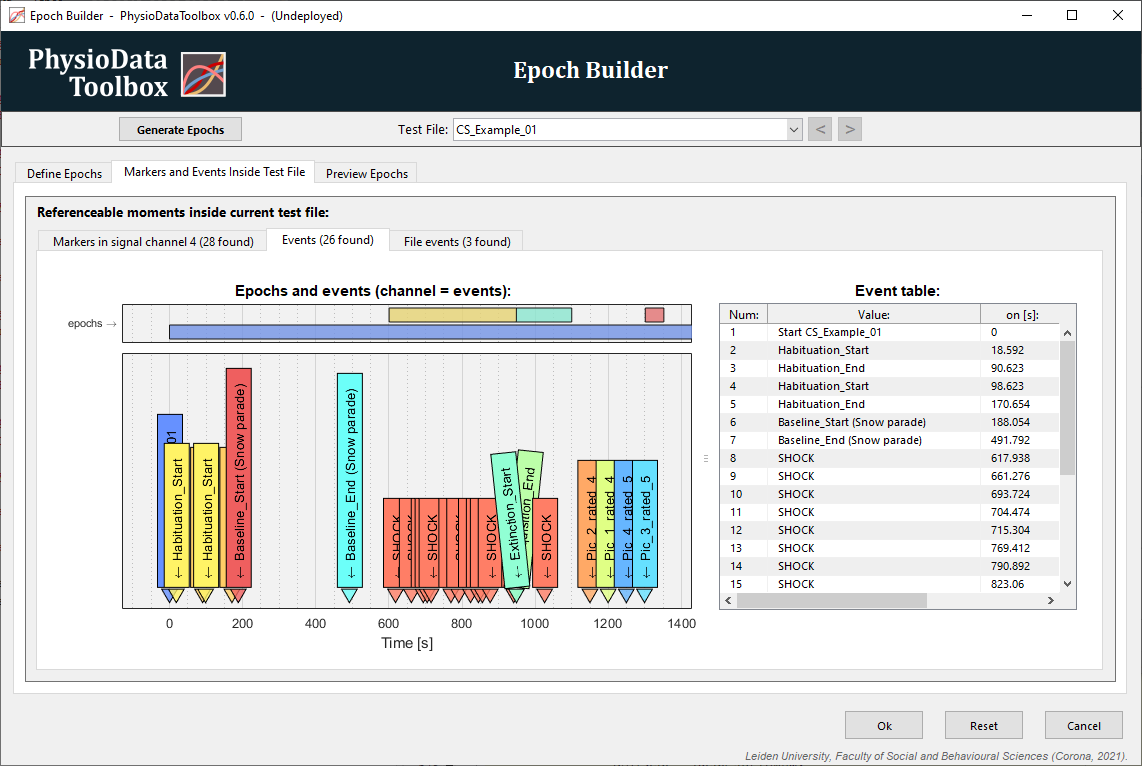
Tab 2: Markers and Events Inside Test File
The second tab, labeled Markers and Events inside Test File, displays all the referenceable events in the current (test) file. The epoch generated by the the current epoch definition table, as defined in tab 1, are shown above each graph. Additionally, the channel code—what needs to be entered in the channel parameter in order to reference the displayed set—is shown in the graph titles.
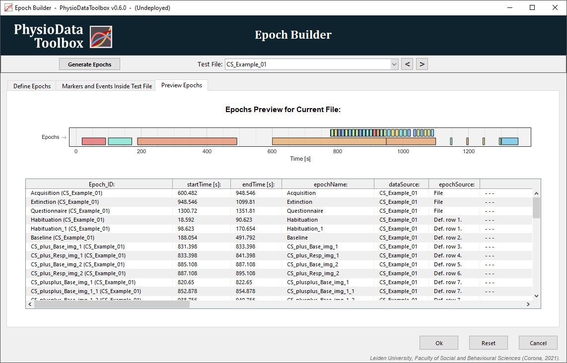
Tab 3: Preview Epochs
The third tab, labeled Preview Epochs, again plots the epochs, but also shows a table with all the data about the generated epochs.
New Epoch Features in v0.6+
The new epoch definition engine is similar to the old version, but features some improvements and a slightly different format. This section presents the main differences.
-
EpochName Column:
The epoch name is now located in the first column rather than the last. -
Dur instead of at:
In the old version, the at parameter (startAt and endAt) determines if the start or the end of a marker is referenced. These parameters no longer appear in the new epoch definition. Instead, use the ‘dur’ keyword in the delay parameters (startDelay and endDelay) to add a delay equal to the duration of the marker (or other event). See this section for more information. -
Dynamic Values, Occurrences and Delays:
Previously, exact values had to be specified. Now, values can be numeric ranges or regular expressions. Additionally, in the previous version, only a single predefined occurrence had to be specified (startOccur and endOccur). Now, multiple occurrences and the last keyword are supported.Similarly, multiple delays can now be specified when defining epochs. See this section for more information.
-
epochModify Deprecated:
The epochModify column no longer appears in the new epoch definition table. If you want to slice an epoch into smaller sections, you will need to use the delay parameters. See this section for more information. -
New Epoch Builder:
The epoch Builder interface has been updated and now features several improvements. Most importantly, users can now right-click inside the epoch definition table’s cells to open context-aware helper menus.
An example of the old epoch definition:
| startChannel | startValue | startDelay | startAt | startOccur | endChannel | endValue | endDelay | endAt | endOccur | epochName |
|---|---|---|---|---|---|---|---|---|---|---|
| 1 | 200 | 0 | on | 2 | 1 | 200 | 10 | off | 2 | epoch |
The equivalent epoch definition in the new Toolbox:
| epochName | startChannel | startValue | startDelay | startOccur | endChannel | endValue | endDelay | endOccur |
|---|---|---|---|---|---|---|---|---|
| epoch | 1 | 200 | 0 | 2 | 1 | 200 | 10 + dur | 2 |
When opening physio data files generates in the old Toolbox version, please make sure that the epochs are resolved as intended.
Events
Next to epochs, the Toolbox can also perform events based analysis. Events are similar to epochs, except they only contain a single time point. Where an epoch has a start time and an end time, an event only has an event time. Events can be created and edited the same way as epochs, with the only difference being that a single time point needs to be defined. An event definition table therefore consists of the following variables: eventTime, eventChannel, eventValue, eventOccur and eventDelay.
Currently, only the IBI module makes use of events.