File Converter
The File Converter is an app that converts various data formats into PhysioData files for use in the Toolbox.
Table of contents
Introduction
The PhysioData toolbox is designed to only analyze standardized PhysioData files, which are MATLAB files with the physioData extension that comply with the PhysioData file specification.
To facilitate the batch conversion of raw physiological data to the PhysioData format, the toolbox includes a File Converter app.
Launching the File Converter
The File Converter can be launched by running PhysioDataToolbox.exe, then clicking the File Converter button on the welcome screen, or by clicking the menu in the top left corner of the Session Manager, then selecting the File Converter.
See the installation page for more information.
Supported File Types
The current version of the File Converter supports the following raw file formats:
- BIOPAC
- VU-AMS
- BioSemi
- LIBC Philips Achieva 3T MRI scanner
- EyeLink
- Tobii
- TSV with signals
- TSV with eye-tracking data
If your raw data is stored in another format, you can still generate PhysioData files for processing in the Toolbox using a custom MATLAB script (more info).
User Interface
Files can be imported into the File Converter by clicking the Select Files button and selecting the correct file type and import options. Once the raw files have been imported, information about their contents is presented in the Current Raw Files table, with each row below the top row representing a single file. The Destination Folder path indicates the location where the converted files will be stored, and can be changed by clicking the Select Folder button.
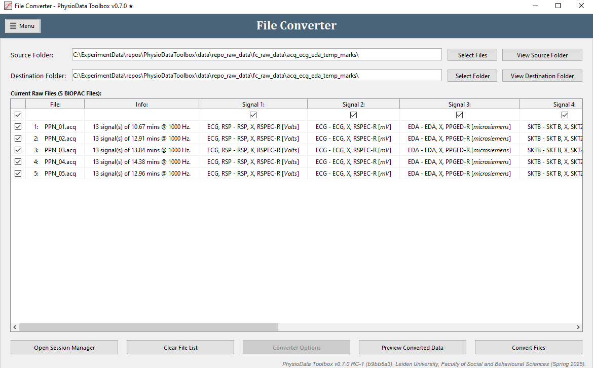
The first column in the Current Raw Files table contains checkboxes used for enabling and disabling individual files for conversion. The File and Info columns to the right of that show the file names and a summary of the file contents, respectively.
In the case that the raw files contain signals, the subsequent columns will show their names and units. Similarly, if a file contains pupil diameter data, columns representing the left and right pupil size data will appear. The checkboxes in the top row can be used to enable and disable individual channels for conversion. It is strongly recommended to not convert data that are not required for analysis.
Below the table, the Open Session Manager closes the File Converter and launches the Session Manager, and the Clear File List button resets the converter to its default empty state. The Converter Options button launches a menu showing custom conversion options for the selected file type. This button is disabled if the file type does not have any custom options, as is the case for BIOPAC files.
Data Previewer
Clicking the Preview Converted Data button converts the first enabled raw file and displays the converted data in a new window called Data Previewer, which is similar to the Toolbox’s Raw Data Viewer. For more information about viewing and navigating through raw data, see the Data Viewers.
The Data Previewer only converts the signals currently enabled for conversion in the Raw Files table (i.e., data in columns where the first row has a checked checkbox). Additionally, if available, the Data Previewer uses the currently set custom converter options when generating data for previewing. These options can be viewed by clicking the custom options button in the main File Converter window (below the table), or the same button in the Data Previewer (to the left of the current file menu). Note that previewing does not actually create a PhysioData file.
File Conversion
The Convert File button in the main File Converter window starts the file conversion process, which, depending on the file type, may take a few minutes to complete. The resulting PhysioData files are always given the same name as their raw file counterparts, with the exception of the extension. Before conversion, make sure that all files are similar and compatible with the selected conversion options.
If the File Converter detects imminent filename collisions, i.e. that similarly named PhysioData files already exist in the destination folder, the following options become available:
-
Skip files that already exist (default):
If this option is left selected, the raw files that would produce a PhysioData files that already exist are not converted. -
Only overwrite the raw data inside the existing PhysioData files:
This option causes the File Converter to only rewrite the raw data inside the PhysioData file, if it already exists, leaving all module’s settings, states and corrections intact. Use this option if for instance you already have modules and correction in the file that you do not want to override, but you do want to change the raw data. -
Completely overwrite existing PhysioData files:
When selected, any preexisting PhysioData file with a conflicting name will be completely overwritten.
BIOPAC Files
The built-in BIOPAC converter supports AcqKnowledge data saved as .acq files or exported as .mat files. Only AcqKnowledge .acq files that comply with the following requirements can be converted:
- File must be saved in an AcqKnowledge v3.9 through v5.0.8, not newer or older.
- All channels must have the same sampling rate.
- All channels must have the same length.
AcqKnowledge data that don’t conform to these requirements can still be exported as .mat files and then converted using the File Converter. Note that when AcqKnowledge saves data as a .mat file, the events (labels) are lost. Marker channels, however, will stay intact.
Alternatively, if the AcqKnowledge files are newer than what the Toolbox supports, the data can be saved as a ‘Windows AcqKnowledge 3 Graph’ inside AcqKnowledge, which should be compatible with the BIOPAC File Converter given that the file conforms to the above-mentioned specifications.
The BIOPAC converter does not feature any custom conversion options.
Marker Channels
When using digital markers, and depending on the experimental design, the BIOPAC AcqKnowledge data may contain 8 digital channels that are only used to calculate a separate 8-bit decimal marker channel. If this is the case, these 8 single-bit channels, usually labeled ‘Digital Input’, should be omitted from conversion as they are not necessary for data analysis. Do this by unchecking the columns pertaining to these bit-channels. The Toolbox attempts to automatically uncheck the bit channels for conversion if it deems them unnecessary.
Performance Issues
Please note that the Toolbox analyzes signals at their native sampling frequency. As such, if the sampling frequency is high, the recording long and/or the PC slow, the Toolbox may become sluggish. To remedy this, consider downsampling the data in AcqKnowledge (Transform → Resample Graph).
Additionally, only convert the channels you seek to analyze.
VU-AMS
The VU-AMS converter supports converting raw 5FS files recorded using the VU-AMS system. All sub-sampled signals are up-sampled to the master sampling rate through linear interpolation and nearest neighbor extrapolation. Note that only the ECG, SCL, DZ, Z0 and BAT channels are extracted from the files, when available.
If the Z0 channel is present, a -dZ/dt channel is generated using a differentiating 256 order FIR filter with a high-pass cutoff frequency of 1 Hz, and a low-pass cutoff frequency of 10 Hz.
The VU-AMS converter does not feature any custom options.
LIBC Achieva MRI
PhysLog files generated by the LIBC Philips Achieva 3T MRI scanner can be converted to the PhysioData format using the LIBC Achieva MRI converter. Note that this converter is designed specifically for use with data from the Leiden University scanner, and may not work as intended on data from other scanners, even those of the same make and model.
The converter makes the following variables from the raw physlog .log files available:
- v1: The first VCG vector.
- v1: The second VCG vector.
- resp: The respiration signal.
- ppu: The ppu (pulse) signal.
- gx: The MR X-gradient.
- gy: The MR Y-gradient.
- gz: The MR Z-gradient.
Additionally, the converter produces a channel which is the average of both v1 and v2 called v1v2avg; i.e. v1v2avg = (v1 + v2) / 2. The scanner also logs physiological trigger events in the mark channel inside the physlog file. These events are converted into 3 synthetic signals with spikes at the locations of triggers: VCG_TRIG, PPU_TRIG and RESP_TRIG.
The converter assumes a sampling frequency of 496 Hz.
The LIBC Achieva MRI converter does not feature any custom options.
Analysis Tips
When using the ECG module to analyze the VCG data, it has been observed that using v1v2avg as the “ECG” channel, and applying a high-pass filter of 8 Hz and a low-pass of 46 Hz–approximately–works adequately across various participants and conditions. Increasing the high-pass filter frequency may further improve the suppression of noise and other cardiac waves.
Note that the ECG module expects an ECG signal in the common mV range. Since this is not the case with the physlog signals, the module’s gain, or the detection and rejection criteria, will need to be modified.
BioSemi
The BioSemi converter can be used to extract physiological signals from .bdf files and save them in the PhysioData format. Since the PhysioData Toolbox cannot analyze EEG data, only other physiological signals present in the file, such as ECG, EMG, skin conductance, etc., should be extracted.
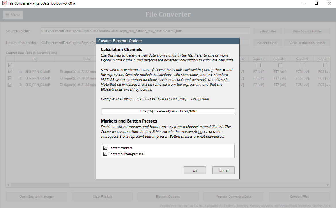
For BioSemi files, the following BioSemi Options can be set:
-
Calculation Channels:
This field can be used to generate new data from signals in the file. This can for example be useful for generating an ECG signal. The BioSemi options window provides a calculation example. -
Markers and Button Presses:
Enables the conversion of Markers and/or Button Presses to markers and labels in the PhysioData file, respectively. By default, both Markers and Button Presses are converted. Note, however, that button presses are not debounced.
Tobii
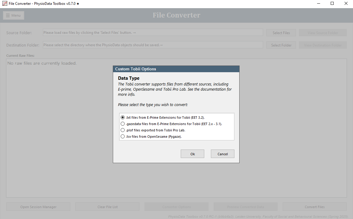
The Tobii converter can convert data recorded with an Tobii eye-tracker, in combination with the following software:
- E-Prime Extensions for Tobii (EET) version v3.2:
Text files with the .txt extension generated in E-Prime with the EET v3.2 plugin. - E-Prime Extensions for Tobii (EET) versions 2.0-3.1:
Text files with the .gazedata extension generated in E-Prime with older EET plugins. - Tobii Pro Lab:
Text files with the .plof extension generated Tobii Pro Lab (TPL). - OpenSesame and PyGaze:
Text files with the .tsv extension generated in OpenSesame with the PyGaze plugin.
E-Prime Extensions for Tobii
The Tobii converter supports EET files with the .gazedata (EET 2.x – 3.1) and the .txt (EET 3.2) extensions. In these modes, the following custom options are available:
-
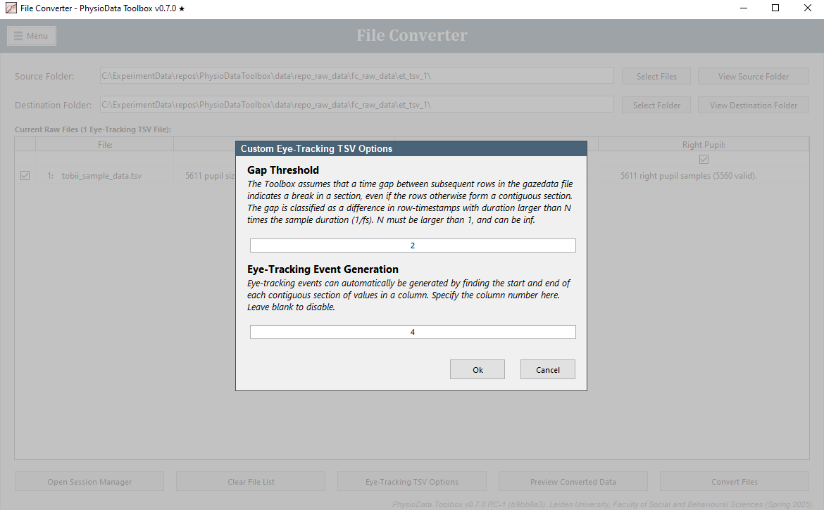
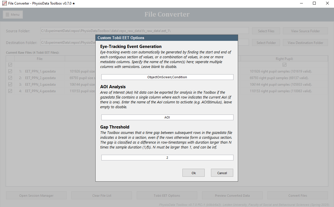
Eye-tracking Event Generation:
In this field, one or more column names of the EET files can be specified. These columns will then be used to generate eye-tracking events by finding the start and end of each contiguous section of values, or a combination of values if multiple columns are used. Leave this field blank to disable this feature. Multiple columns can be separated by a semicolon. See the Experimental Design Considerations section below for more information. -
AOI Analysis:
The Toolbox can perform simple area of interest (AOI) analysis if the AOI hits have been pre-calculated, and tabulated as a single column with each row indicating the currently looked-at AOI. The name of this column can be entered into the AOI Analysis field to activate the AOI analysis feature, of the field can be left empty to deactivate it. In EET 3.2 files, the ComponentName column can be used for AOI Analysis. The ComponentName column is automatically created in EET 3.2 files and contains the (sub)object or slide state that is currently being looked at. See the Experimental Design Considerations section below for more information. -
Gap Threshold: The Toolbox assumes that a time gap between subsequent rows in the gazedata file indicates a break in a section, even if the rows otherwise form a contiguous section. The gap is classified as a difference in row-timestamps with duration larger than N times the sample duration (1/fs). N must be larger than 1, and can be inf. Setting it to inf effectively turns off the above mentioned assumption. The default value of 2 should work in most cases.
Experimental Design Considerations
There are a few considerations one should keep in mind when designing an E-Prime task with EET eye tracking and when aiming to analyze the data with the PhysioData Toolbox.
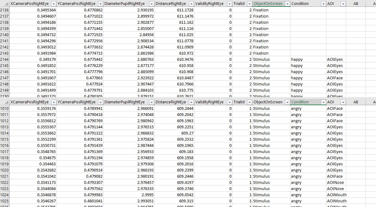
The first is the Eye-tracking Event Generation column(s). This column should hold data relevant for event generation (usually String data) and is crucial, as it will be impossible to create epochs without it. The event generation column could for example hold the currently running object in E-Prime, such as “Stimulus” or “Fixation”. When segmentation requires more detailed information, multiple columns can be used for event generation. For example, the currently running object, and the condition of the current trial (e.g. “congruent” and “incongruent”). See the figure below for example event generation columns in the gazedata file.
By default, E-Prime does not save any event data in the gazedata file, these data have to be defined by the user. See here for instructions on how to incorporate Tobii eye tracking in an E-Prime experiment, including adding event data to the gazedata files.
Another consideration is the AOI column used for the AOI Analysis (not relevant when only pupil data is analyzed). The AOI column should hold the name of the AOI the participant was looking at. By default, E-Prime 3 (when used with EET 3.2) saves a variable called ComponentName. This variable holds the component of the experiment (e.g. Slide sub-object) the participant is looking at. This variable could function as an AOI column. However, whether this variable is suited should be evaluated. See the figure below for an example AOI column in the gazedata.
It is strongly recommended to convert gazedata from an initial pilot to check whether the event generation column(s) and (if applicable) the AOI column are sufficient for the purpose of the study, before starting data collection.
Tobii Pro Lab
The Tobii converter can convert plof (Pro Lab Output Format) files, which can be generated in Tobii Pro Lab. The converter has been tested with plof version 2.2 through 2.5, and imports the following data, if present:
- Pupil size:
Pupil size data is converted for use with the Pupil Size module. - AOI:
The area of interest (AOI) hits are converted for use with the AOI module. - Events:
All events in theStimulusandEyetrackerCalibrationcategory are converted for use in epoch generation. These events are saved in the eye-tracking dataset, and can be referred to using the channelET.events.
The plof converter does not feature any custom settings.
OpenSesame and PyGaze
The Tobii converter can convert tsv files produced by running eye-tracking experiments using OpenSesame and PyGaze, and a Tobii eye-tracker. The converter was tested with OpenSesame 3 and 4, PyGaze 0.7; and the following Tobii eye-tracker models: X2-60, X3-120, Fusion, Nano and Spectrum.
For OpenSesame/PyGaze tsv files, the following option is available:
- OpenSesame time Variable Name:
The name of the variable indicating the current OpenSesame time. See below for details. If the field is left blank, the messages in the tsv files are parsed as they are, without any time correction or trial generation.
Experiment Structure and Conversion Actions
A typical PhysioData Toolbox-compatible OpenSesame/PyGaze experiment has the following structure:
- Initialization:
The pygaze_init object in OpenSesame initializes PyGaze and the Tobii eye-tracker. - Time logging:
An inline_script object can be used to log the current OpenSesame time by placing the following code in its Run tab:eyetracker.log_var('cur_os_time', clock.time()). This is necessary for mapping the OpenSesame times to the eyetracker timestamps, see below. It is advised to add a second instance of this object at the end of the experiment to minimize the effect of clock drift. - Trials:
Each trial should consist of the following eye-tracker control objects:- Start of trial:
The pygaze_start_recording object starts the recording of the current trial. Keepstart_trialas the status message string. - Log custom variables (optional):
Any number of pygaze_log objects can be used inside the current trial to mark events, or log variables belonging to the current trial. In this usage, the Automatically log all variables checkbox should be unchecked, and the message manually entered in the object’s textbox. - End of trial:
The pygaze_stop_recording object ends the recording of the current trial. Keepstop_trialas the status message string, and optionally append it with a whitespace, followed by a suffix (e.g. trial name, trial conditions, etc.). This suffix will be used to label the trial, see below. A valid stop trial message is e.g.stop_trial CAT DOG. - Log OpenSesame variables:
The pygaze_log object logs the current values of all OpenSesame variables when the Automatically log all variables checkbox is enabled. This includes the onset times of each OpenSesame object, which is used by the Toolbox to create corresponding events that can be referenced when generating epochs.
- Start of trial:
When converting tsv data, the converter performs the following actions:
- Pupil size:
The pupil size data is converted for use with the Pupil Size module. - Time correction and event generation:
The converter uses the ‘cur_os_time’ messages to calculate the OpenSesame/eye-tracker time offset, and creates events corresponding to the actual onset time of each OpenSesame object of which the onset time was logged. These events are given the name of the corresponding object, prepended by ‘OBJECT: ‘. - Trial generation:
The converter finds each pair of ‘start_trial’ and subsequent ‘stop_trial’ messages, and considers the interval between them as being a single trial. For each trial, and event spanning its duration named ‘trial <TRIAL NUMBER>’ is created. Additionally, the converter extracts the suffix of each stop_trial message, if present, and appends it to all events in the corresponding trial using the following format: ‘<ORIGINAL VALUE> ()'.
The events created by the converter can be referenced in the by setting the startChannel or endChannel to et.events, see the Epochs page.
EyeLink
The EyeLink converter can be used to extract raw pupil-size data from SR research’s EyeLink .edf files. The converter will also parse messages and digital inputs, if present, into referenceable events.
This converter features the following custom options:
-
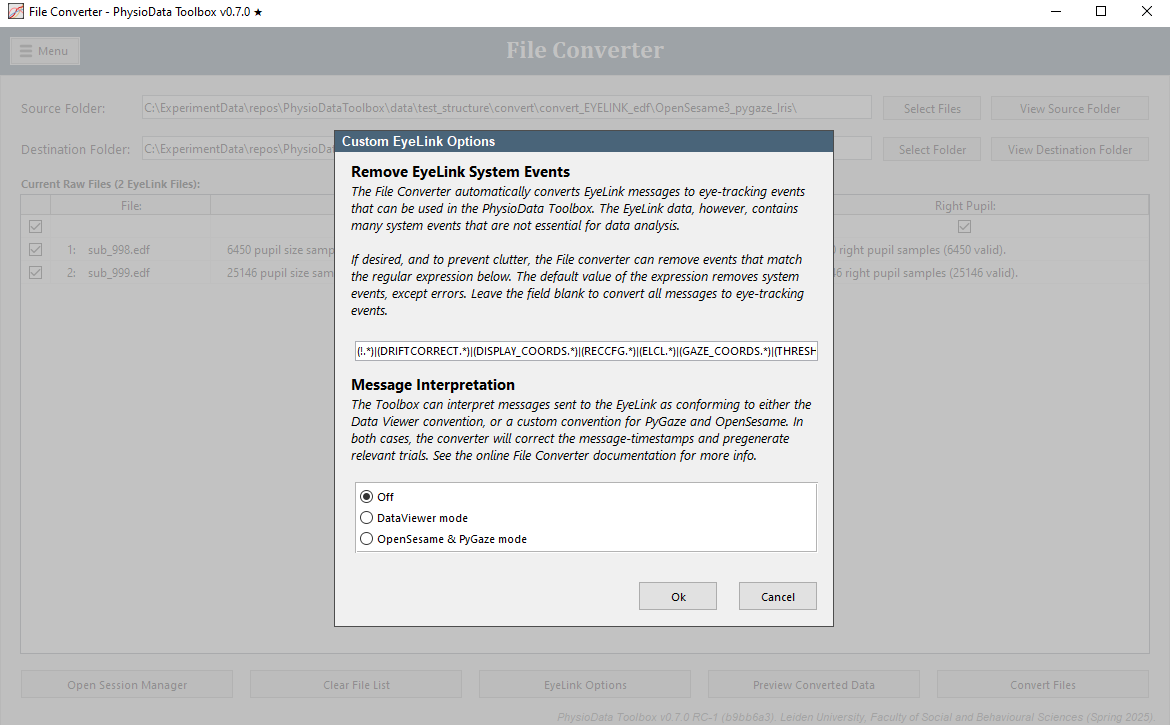
Remove EyeLink System Events:
The File Converter converts all messages available in the .edf file to eye-tracking events, except the events that match the regular expression specified in this field. Leaving the field blank converts all messages. Many EyeLink system-events are not actually used by the PhysioData Toolbox and can therefore be omitted from conversion. The default value removes these system-events. -
Message interpretation:
- Off:
The data is not interpreted in any special way and left as is. - DataViewer mode:
The data is interpreted as conforming to a subset of the DataViewer convention, namely:- Message offset correction:
If messages were sent with an time-offset prefix as defined by DataViewer, then the timestamps of those messages can be corrected accordingly by the File Converter. These messages should have the following format:\<offset> \<msg>, where\<offset>is the message delay in ms. - Trial generation:
Trials are generated from ‘TRIALID’ and ‘TRIAL_RESULT’ messages-pairs. At least one trial must be present. These trials are converted into pregenerated epochs by the converter. Additionally, trial variables (messages in form of!V TRIAL_VAR <NAME> <VALUE>) are parsed and added as epoch metadata.
- Message offset correction:
- OpenSesame and PyGaze mode:
The data is interpreted as conforming to a predefined OpenSesame and PyGaze convention. For more information, please see the OpenSesame and PyGaze section above, which is part of the Tobii Converter documentation, but also holds true when using and EyeLink with OpenSesame and PyGaze.
- Off:
\
Experimental Design Considerations
When recording data with an EyeLink eye-tracker for the purpose of pupillometry, SR Research suggests:
- Use Head Stabilized Mode.
- Keep camera distance fixed for all participants.
- Remote mode not advised, but if you have no choice, try to limit forward and backwards movements, and use the 25mm lens.
For more information on collecting pupil size with EyeLink, see Recording and Analyzing Pupil Data (Pupillometry).
Analysis Tips
The Pupil Diameter module expects the pupil diameter to be in mm. This is not the case for EyeLink data, where pupil diameter is reported in arbitrary pixels. Therefore, the module’s gain or detection and rejection criteria will need to be modified.
EyeLink pupil diameter data can be converted to mm, for instructions see this FAQ on the SR Research Support Forum (log-in required). Converting the pupil diameter to mm can be done in the PhysioData Toolbox, by using the Gain setting in the Pupil Diameter module, or it can be done after processing the data in the PhysioData Toolbox, in for example Excel, R or SPSS.
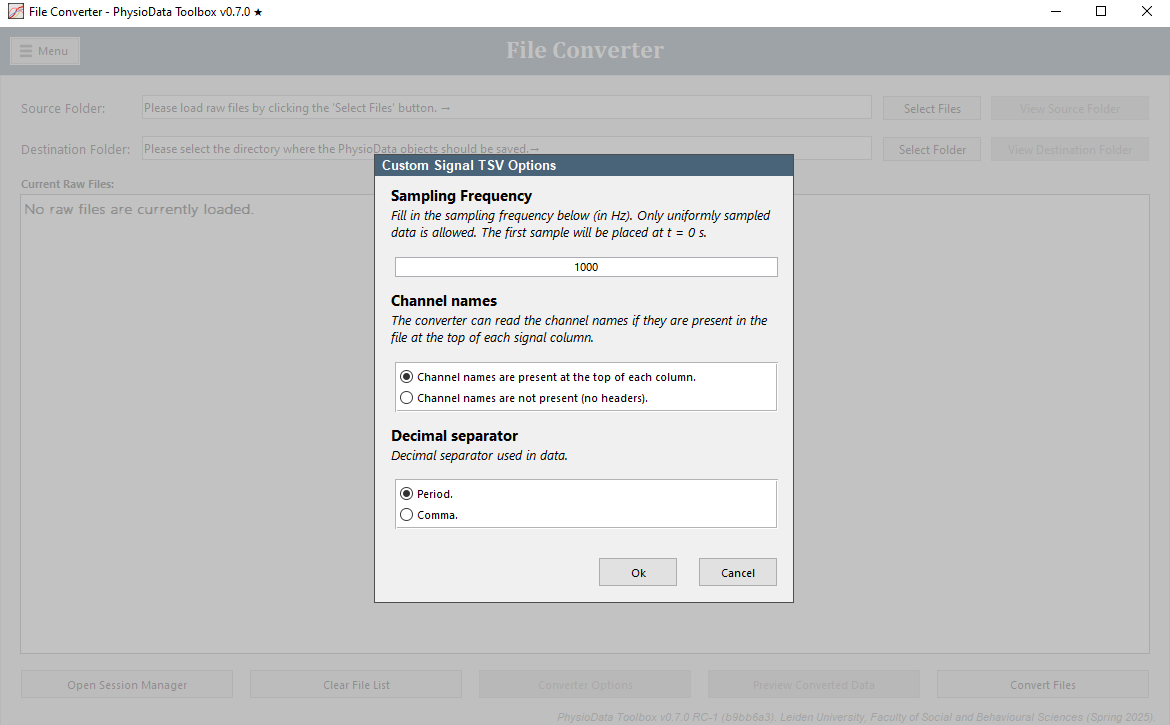
Signal TSV File Converter
The Signal TSV File converter can convert arbitrary signals saved as standard tabular tsv files into the PhysioData files. These tsv files must contain uniformly sampled data, with a sampling frequency between 100 and 10000 Hz, and a duration of at least 10 seconds. Each signal (aka channel) should live in its own column, and all channels must have the same sampling rate. Additionally, all channel elements must be convertible to numerical values.
The table may also contain events in the last column, in which case the converter will convert the strings in the event columns into referenceable events that can be used when generating epochs. Each string, or section of strings, is converted to start and end labels. Blank elements indicate no events. Download an example file here.
The TSV file should have the following specification:
- File extension:
tsv. - Variable separator: tab.
- Decimal separator: comma or period, see below.
- Header: optional, see below.
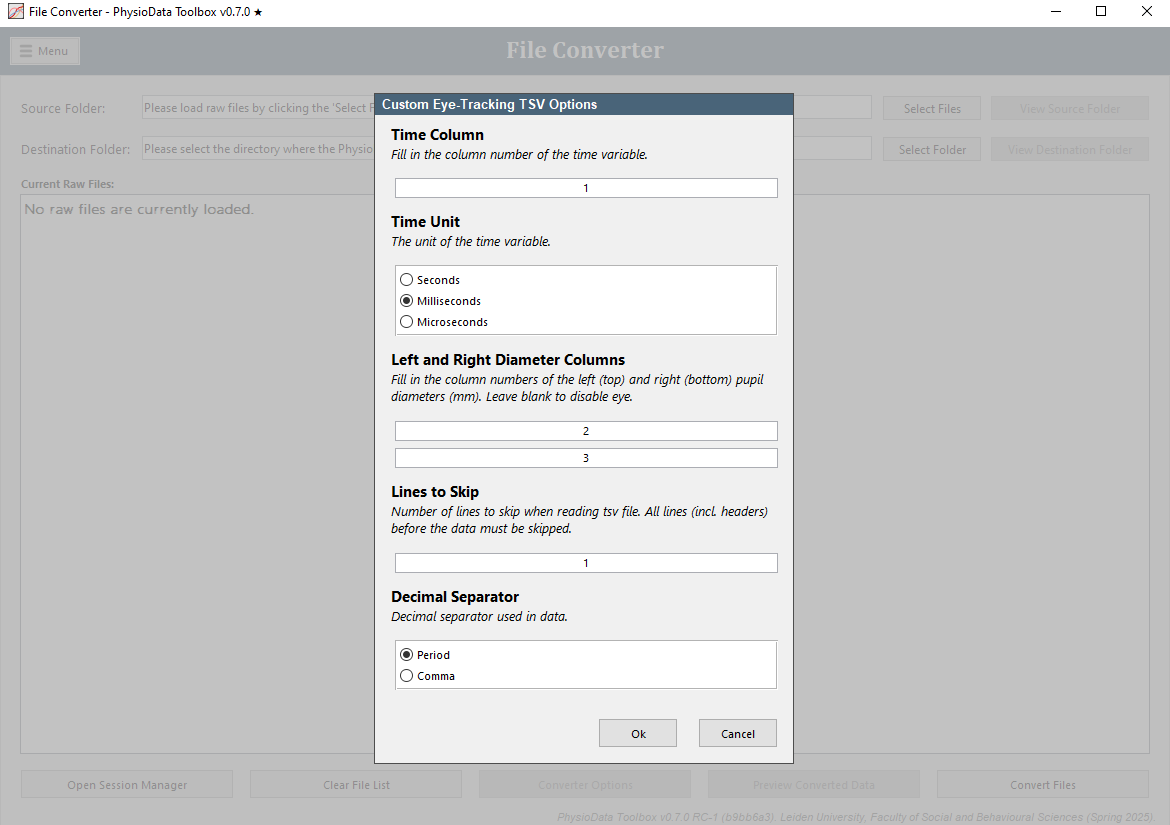
Eye-Tracking TSV File Converter
The eye-tracking TSV file converter can convert arbitrary eye-tracking data saved as standard tabular tsv files into the PhysioData files. The converter can process left and/or right pupil size data, and event data. Area of Interest hits are not currently supported.
The data may be in any column, which needs to be specified by the user. Download an example file here. The example file can be loaded using the default setup-options. Once loaded, click on the Eye-Tracking TSV Options button and set the events column to 4, which is the column in which the events are located. The file showcases two types of events; contiguous sections–the Practice section–and discrete events.
The TSV file should have the following specification:
- File extension:
tsv. - Variable separator: tab.
- Decimal separator: comma or period, see below.
- Header: any number of header lines can be skipped, see below.